UPDATE: Under certain circumstances it is possible that this panel can produce flats with moderate to severe banding. An explanation of why this happens and how to fix it is given in this article.
Introduction
Part of the calibration process associated with astrophotography involves taking "flats" which capture the unevenness of the image field due to phenomena such vignetting and dust particles on the sensor. A professional flats panel is unfortunately rather expensive and so many people choose the diy approach. This is one such project based heavily upon others documented in various places around the net.
Operation
The principle is simple: an LED tracing lightbox (available cheaply on eBay) is used and the intensity of the panel's light is varied using pulse-width-modulation which is controlled via an MCU - in this case an Arduino clone. Software on the Arduino also communicates with a PC over a serial connection and so the panel can be controlled by software such as Sequence Generator Pro.
Power
Often such devices, including the LED panel, are powered over USB from the PC controlling them but in this project a more conservative approach is taken. The LED panel used here, at 5V DC, draws around 2A of current and this is far more than the Arduino, and most USB ports, can provide. MCUs such as the Arduino UNO are only rated to provide up to 0.5A from their 5V pins and are often protected via a 0.5A poly fuse. When operated using PWM the RMS current drawn should really not exceed this limit
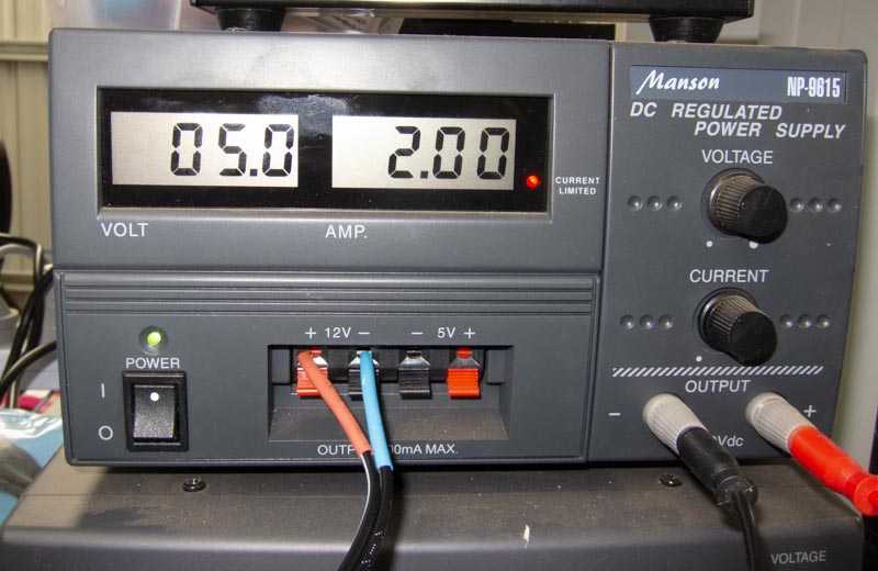
In practice the panel will be used quite dimly, and hence at much lower RMS current, so it may be alright to use USB power provided care is taken and the PWM percentage is kept very low.
In this case the maximum current was 2.0A and, since power is proportional to the square of current,
P = I2R
keeping the current below 0.5A means keeping the power down to one-sixteenth of full - that's just 6.25%. Too be safe, in this design a separate power supply is used to driver the panel's LEDs. The system is driven nominally by 12V since most astrophotography rigs will have some source of 12V DC.
The schematic diagram is given below.
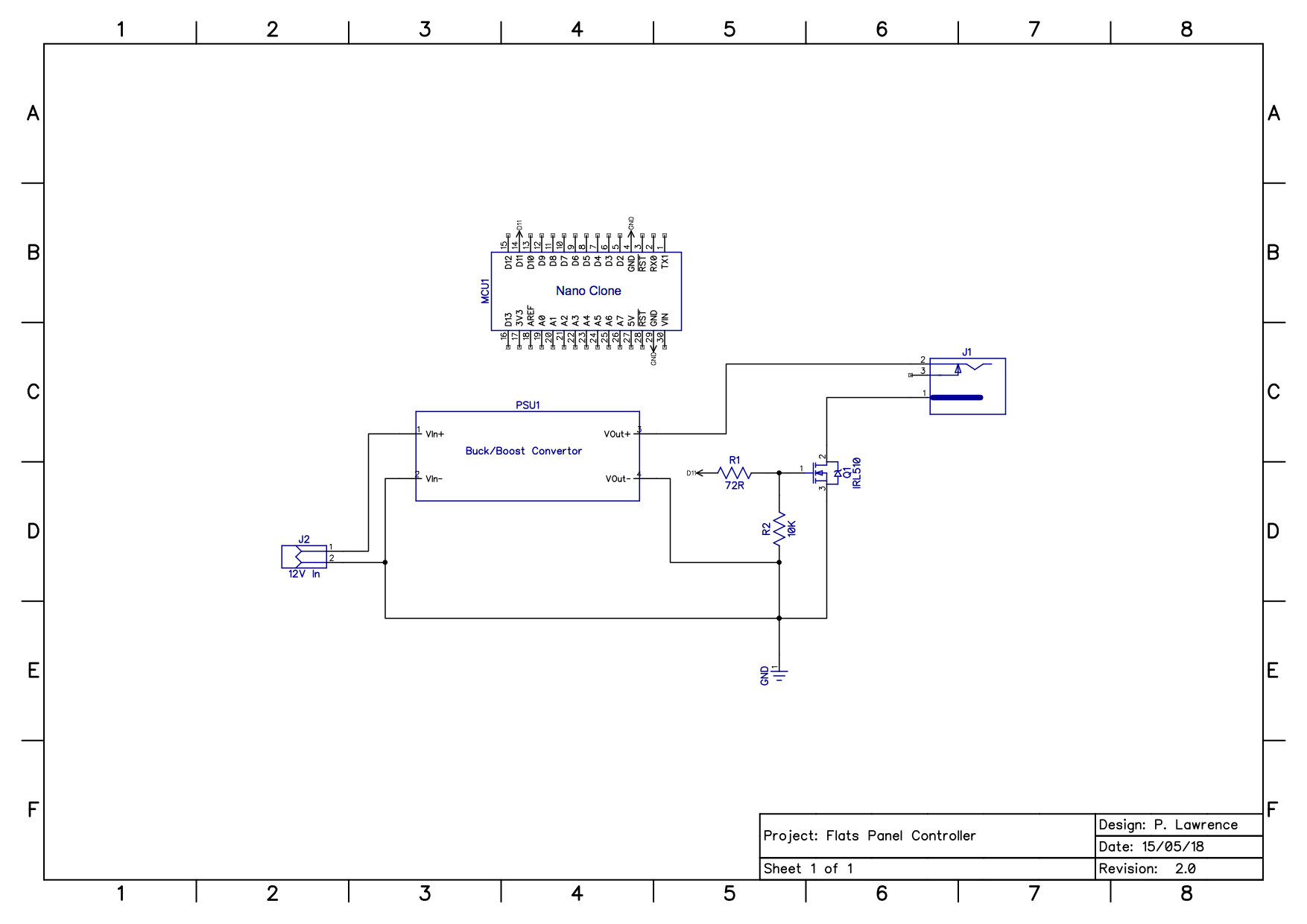
Using a whole Arduino for an application like this, which uses only a single I/O pin is overkill but the convenience of having the USB/Serial interface built in, and the fact that clones such as this are cheap (~$4) makes it a sensible choice rather than building an MCU circuit from scratch. .
The 12V supply is bucked down to 5V via a DC-DC convertor and, once again, the low cost of prebuilt buck/boost convertors (also ~$4) means it is not worth the effort of creating a custom circuit. This 12V supply is fed to the LED panel via a logic-level MOSFET whose gate is controlled by an Arduino pin. The MOSFET has a thermal resistance (junction-to-ambient) of 63ºC/W and a maximum junction temperature of 175ºC so, theoretically, it should be able to handle 100% power without a heatsink. However, if the intention were to operate it at that level for prolonged periods a heatsink would be advisable. In this project no heatsink was used.
Construction
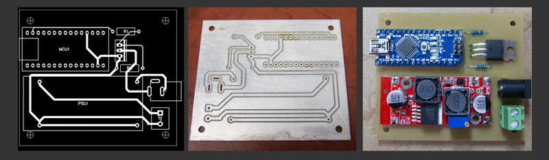
PCB
For ease of construction the pcb shown below was used to mount the components. A dxf of the board is available in the Downloads section at the end of this article.
LED Panel
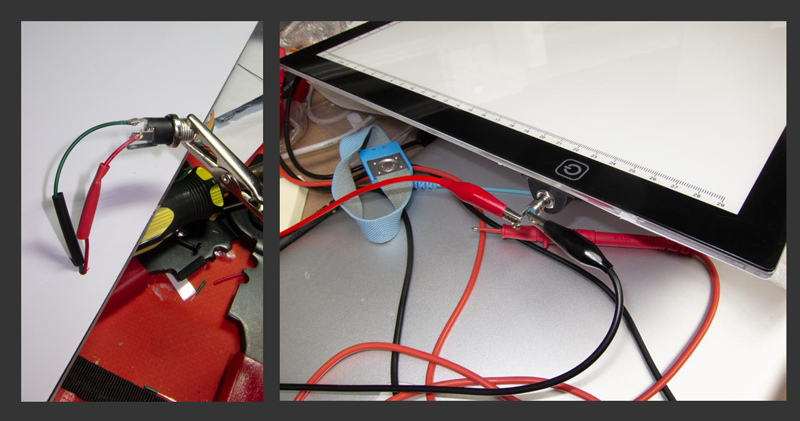
To use the LED panel it's first necessary to peel off part of its backing (near the USB socket) and remove the circuit board already installed. This circuit allows the touch pad on the front of the panel to turn the LEDs on and off and to change their brightness. Once that board is removed and the LED wires desoldered from it the panel can be connected to the Arduino circuit.
You may find that all of the LEDs in the panel are on a single circuit (one pair of wires) or, as was the case with this panel, two separate circuits. If there are two circuits just solder them together and if necessary extend with extra wire. Always be careful to make sure the two circuits keep the same polarity. Pierce a small hole in the back of the panel and pass these wires out through it.
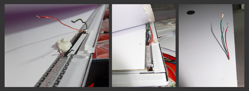
Once this is done a suitable jack can be attached to the back of the panel to simplify connecting the electronics to the panel. In this case 2.1/5.5mm female dc connector was used. A small receptacle to mount the socket was printed in ABS and attached to the back of the panel with double-sided tape. OpenSCAD and stl files for this part are also available for download below.
Enclosure
To house the electronics a small case was constructed out of acrylic sheet by cutting out the following pieces. A dxf file of the design is available in the Downloads section at the end of this article.
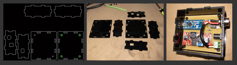
The tabbed/notched design of the case allows the whole thing to be held together with just two M3 machine screws through holes in the lid which are aligned with two of the holes holding the circuit board in place.
Note that all of the interior corners are "dog-boned" so that the corresponding tabs will fit neatly. If this is not done then the internal corners will be rounded with the radius of the rotary tool used to cut them and so the tabs will not fit in.

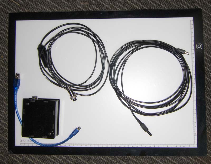
All that remains then as far as construction is concerned is to make up or acquire the necessary cables. Three are required:
- A USB cable to connect the PC to the Arduino box.
- Power cable to connect from the 12V source to the electronics box - in this case a male cigarette lighter plug to a male, 2-pin aviation connector (of the type used for the 12V input on mounts such as the SkyWatcher AZ-EQ6-GT).
- A 5V cable to connect the electronics to the panel - a cable with a 2.1/5.5mm male dc plug on each end.
The finished device is shown below.
Software
Of course, none of this is of any real use without software. The Arduino needs software to control the panel, send and receive serial messages between itself and the PC and there must be some kind of software on the PC to communicate with the Arduino.
Sequence Generator Pro
If you are running Sequence Generator Pro (a Windows only programme) to control your rig then the simplest solution is to download the software here and upload it to the Arduino. This software was developed by Jared Wellman, one of the developers of SGP. It allows the panel to mimic an Alnitak Flat-Man which can be controlled via SGP to automate the taking of flats. Before loading the file the line,
volatile int ledPin = 13;
must be changed to
volatile int ledPin = 11;
Custom Software
However, this project is not going to be used with SGP, and ultimately not on Windows, and so a slightly different approach was taken.
The Alnitak command sequences (documented here) rather peculiarly use CR and LF characters as message terminators which can make debugging the software unnecessarily tedious. In this project the CR was replaced with the '<' character and the LF with a tilda (~). In addition, a more object-oriented approach was used.
The code is shown below and is available for download at the end of this article.
#define PANEL_PIN 11  //  The digital PWM pin that controls the LED panel.

// These defines are required to make things compatible with the Alnitak device, and hence Sequence Generator Pro.
// Please note however, this code had not been tested with Sequence Generator Pro.

//#define CMD_END chr(13)
//#define RESP_END chr(10)
//#define CMD_LENGTH 5
//#define ID "19"  //The device ID for an Alnitak FlatMan.
//#define VERSION "001"
//#define ERROR_COMMANDS false

// These defines are for my own device and are not compatible with Sequence Generator Pro.

#define CMD_END '<' //chr(13)
#define RESP_END '~' //chr(10)
#define CMD_LENGTH 5
#define ID "PL"  //A unique device ID for this panel.
#define VERSION "1.0"
#define ERROR_COMMANDS true

void ProcessCommand(char *buffer);
void ProcessError(char *buffer, char *error);
void ProcessPing(char *);
void ProcessOpen(char *);
void ProcessClose(char *);
void ProcessLightOn(char *);
void ProcessLightOff(char *);
void ProcessSetBrightness(char *);
void ProcessGetBrightness(char *);
void ProcessGetState(char *);
void ProcessGetVersion(char *);

/*
 * Class to represent the light panel.
 */

class TPanel {
  public:
    void SetBrightness(byte value);
    byte GetBrightness();
    void SwitchOn();
    void SwitchOff();
    bool GetState();
    TPanel(bool state, byte level, byte pin);
  private:
    bool on;
    byte brightness;
    byte pin;
};

/*
 * TPanel member functions.
 */

void TPanel::SetBrightness(byte value) {
  brightness = value;
  if(on) {
    analogWrite(pin, brightness);
  }
}

byte TPanel::GetBrightness() {
  return brightness;
}

void TPanel::SwitchOn() {
  analogWrite(pin, brightness);
  on = true;
}

void TPanel::SwitchOff() {
  analogWrite(pin, 0);
  on = false;
}

bool TPanel::GetState() {
  return on;
}

TPanel::TPanel(bool state, byte level, byte ch) {
  on = state;
  brightness = level;
  pin = ch;
  pinMode(pin, OUTPUT);
  if(on) {
    analogWrite(pin, brightness);
  } else {
    analogWrite(pin, 0);
  }
}

/*
 * Create an instance of the Panel
 */

TPanel panel(false, 0, PANEL_PIN);

void setup() {
  Serial.begin(9600);
}

/*
 * Mainloop checks for serial data and processes it.
 */

void loop() {
  if(Serial.available()) {
    char buffer[15] = "";
    Serial.readBytesUntil(CMD_END, buffer, 14);
    ProcessInput(buffer);
  }
}

/*
 * Check that the command has the correct leading character
 * and is the correct length.
 */

void ProcessInput(char *buffer) {
  if(buffer[0] != '>' || strlen(buffer) != CMD_LENGTH) {  // This is not a command so parse it as an error.
    ProcessError(buffer, "Command is not correctly formed.");
  } else {
    ProcessCommand(buffer);
  }
}

/*
 * Determine the command type and call the appropriate function.
 */

void ProcessCommand(char *buffer) {
    switch(buffer[1]) {
      case 'P':
       ProcessPing(buffer);
        break;
      case 'O':
       ProcessOpen(buffer);
        break;
      case 'C':
       ProcessClose(buffer);
        break;
      case 'L':
       ProcessLightOn(buffer);
        break;
       case 'D':
       ProcessLightOff(buffer);
        break;
       case 'B':
       ProcessSetBrightness(buffer);
        break;
      case 'J':
       ProcessGetBrightness(buffer);
        break;
      case 'S':
       ProcessGetState(buffer);
        break;
      case 'V':
       ProcessGetVersion(buffer);
        break;
    }
}

/*
 * Processing for when an error occurs.
 */

void ProcessError(char *buffer, char *errorText) {
  if(ERROR_COMMANDS) {
    Serial.print("*E");
    Serial.print(buffer);
    Serial.print(errorText);
    Serial.print("~");
  }
}

/*
 * Send the passed response back over the serial port.
 */

void SendResponse(char *response) {
  Serial.print(response);
}

/*
 * Functions to process each of the commands.
 */

void ProcessPing(char *cmd) {
  char response[15] = "";
  sprintf(response, "*P%2sOOO%c", ID, RESP_END);
  SendResponse(response);
}

void ProcessOpen(char *cmd) {
  char response[15] = "";
  sprintf(response, "*O%2sOOO%c", ID, RESP_END);
  SendResponse(response);
}

void ProcessClose(char *cmd) {
  char response[15] = "";
  sprintf(response, "*C%2sOOO%c", ID, RESP_END);
  SendResponse(response);
}

void ProcessLightOn(char *cmd) {
  char response[15] = "";
  panel.SwitchOn();
  sprintf(response, "*L%2sOOO%c", ID, RESP_END);
  SendResponse(response);
}

void ProcessLightOff(char *cmd) {
  char response[15] = "";
  panel.SwitchOff();
  sprintf(response, "*D%2sOOO%c", ID, RESP_END);
  SendResponse(response);
}

void ProcessSetBrightness(char *cmd) {
  char response[15] = "";
  bool error = false;
  byte value = 0;
  for(int i=2;i<5;i++) {
    if(!isDigit(cmd[i])) {
      error = true;
    }
  }
  if(!error) {
    value = 100*(cmd[2]-'0') + 10*(cmd[3]-'0') + (cmd[4]-'0');
    if(value > 255) {
      ProcessError(cmd, "Brightness exceeds limit (255).");
    }
    panel.SetBrightness(value);
  } else {
    ProcessError(cmd, "Invalid brightness level");
  }
  sprintf(response, "*B%2s%03d%c", ID, value, RESP_END);
  SendResponse(response);
}

void ProcessGetBrightness(char *cmd) {
  char response[15] = "";
  byte value = panel.GetBrightness();
  sprintf(response, "*J%2s%03d%c", ID, value, RESP_END);
  SendResponse(response);
}

void ProcessGetState(char *cmd) {
  char response[15] = "";
  sprintf(response, "*S%2s%1d%1d%1d%c", ID, 0, panel.GetState()?1:0, 0, RESP_END);
  SendResponse(response);
}

void ProcessGetVersion(char *cmd) {
  char response[15] = "";
  sprintf(response, "*V%2s%3s%c", ID, VERSION, RESP_END);
  SendResponse(response);
}
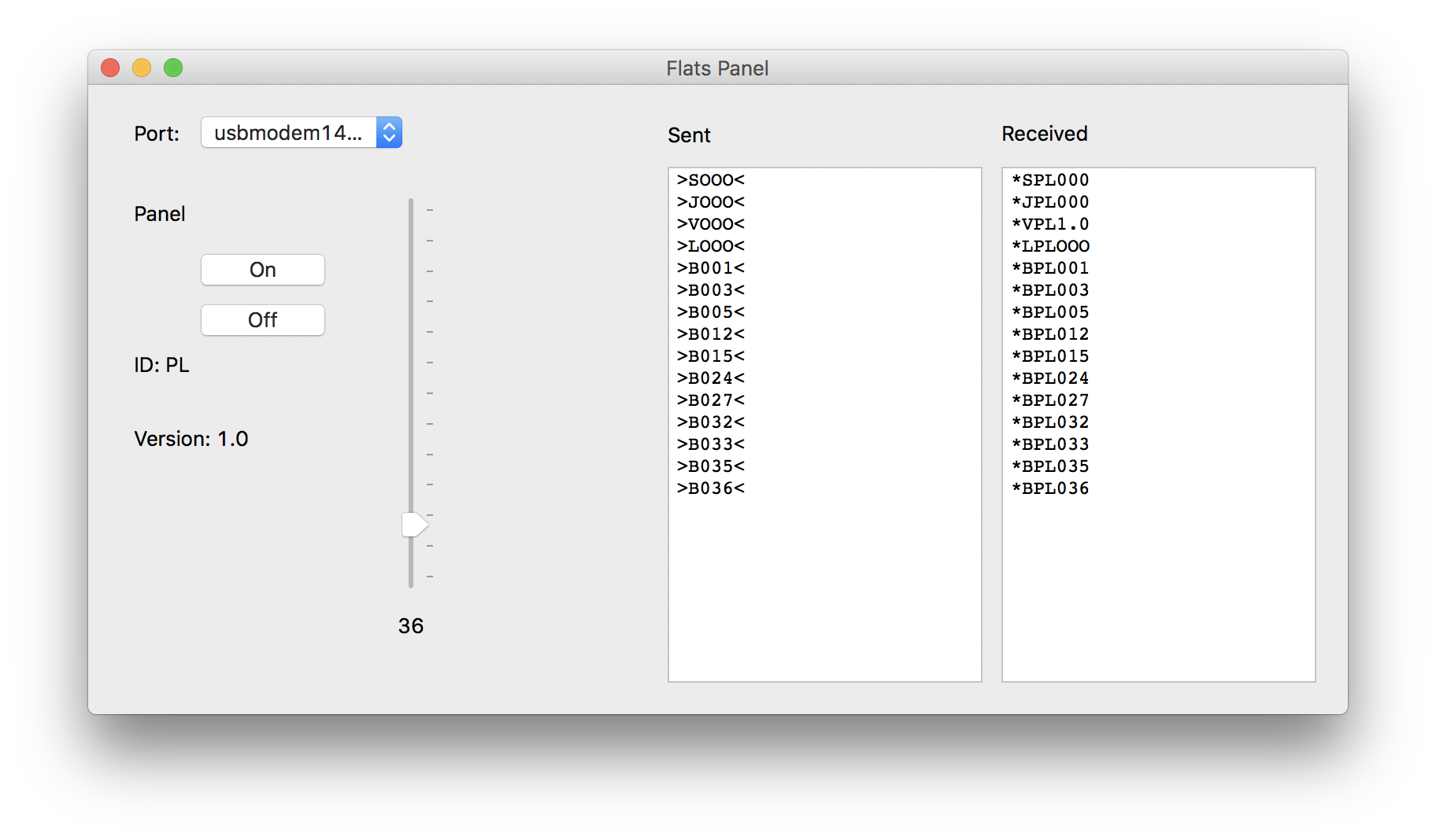
To test the code a simple PC programme was developed that allows connection to the panel and control of the brightness via a slider. It is also available to download below for Mac, Windows, Linux and Raspberry Pi.
Downloads
Printed Circuit Board
Printed circuit board traces, holes and outline:
Enclosure
Acrylic enclosure panels:
Panel socket receptacle:
Software
Arduino code:
Test programme:
MacOS
Windows
Linux
Add new comment